
ConvertersAvailable
Frequency to Period Converter
Convert frequency to period and period to frequency for clocks, PWM, RF, and timing calculations.
Calculator category
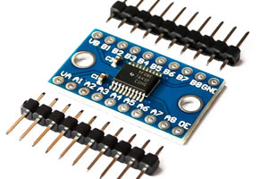
Electronics converters help engineers move between units, measurement systems, and numeric formats used in circuit design, PCB layout, RF calculations, wiring, and embedded systems. This category is focused on practical engineering conversion calculators rather than broad everyday unit conversion.
Current tools include frequency-to-period conversion for clocks and timing, AWG wire gauge to mm² conversion for conductor diameter and cross-sectional area, dBm to watts conversion for RF power levels, and hexadecimal, decimal, and binary conversion for firmware debugging, digital registers, and data inspection.
Use these tools during component selection, wire sizing, PCB design checks, RF measurement review, embedded troubleshooting, clock and PWM analysis, and electronics laboratory work. Results are intended for engineering estimates and workflow support; verify final designs against datasheets, standards, and measured results.
Available Calculators
4
Engineering Applications
6
Each listed tool links to a working calculator with engineering inputs, formulas, examples, notes, and related resources.
Convert frequency to period and period to frequency for clocks, PWM, RF, and timing calculations.
Convert American Wire Gauge sizes to conductor diameter and cross-sectional area for wiring and PCB applications.
Convert RF power between dBm, dBW, watts, milliwatts, and microwatts.
Convert number bases and analyze bit patterns, two's complement values, registers, and digital data.
Choose the calculator that matches the decision you need to make: decode a component marking, size a value, check a frequency response, estimate loss, or verify a safety margin. A category page is useful only when it helps you reach a working tool, so this page lists released calculators only.
Calculator results depend on unit choices, idealized formulas, tolerance, temperature, frequency range, and component limitations. Review the formula and engineering notes on each calculator page before using the result in a schematic, BOM, or PCB layout.
Use the calculated value as a design reference, then confirm it against datasheets, derating curves, layout parasitics, measurement conditions, and manufacturer limits. The related guides below provide background when a calculation needs more context.
Support reference
ECParts currently includes converters for frequency and period, AWG wire gauge and conductor dimensions, RF power levels such as dBm and watts, and digital number bases such as hexadecimal, decimal, and binary. The category is focused on electronics engineering workflows rather than everyday consumer unit conversion.
A general unit converter may cover broad measurements such as distance, mass, or cooking units. ECParts Converters prioritize electrical engineering tasks such as timing conversion, wire gauge sizing, RF power conversion, embedded number formats, PCB design checks, and component selection workflows.
Yes. The AWG converter is useful for estimating conductor diameter and cross-sectional area when reviewing wiring, harnesses, and PCB-related current paths. For final current rating decisions, also check insulation, temperature rise, installation conditions, and applicable standards.
dBm to watt conversion is commonly used in RF measurements, transmitter output power checks, receiver sensitivity work, amplifier gain review, and lab instrument readings. It helps engineers compare logarithmic RF power units with absolute watt, milliwatt, or microwatt values.
Embedded systems and digital electronics often use hexadecimal registers, binary bit fields, decimal values, masks, and two's complement representations. A number base converter helps with firmware debugging, protocol analysis, register configuration, and hardware bring-up.
Converter results are intended to reduce arithmetic mistakes and speed up engineering workflows. Final designs should still be checked against component datasheets, safety margins, measurement data, PCB constraints, environmental conditions, and any standards that apply to the product.
Engineering Guide
Learn engineering unit conversions for electronics, including SI prefixes, powers of ten, engineering notation, resistance, capacitance, inductance, voltage, current, power, energy, frequency, time, PCB units, and common conversion mistakes.
22 min · Beginner
Engineering Guide
Learn frequency, period, time, PWM, phase delay, angular frequency, wavelength, RPM, and signal timing conversions using reciprocal formulas and correct engineering units.
24 min · Intermediate
Engineering Blog
Avoid common engineering unit conversion mistakes involving SI prefixes, milli vs mega, micro vs nano, frequency and period, watts vs watt-hours, PCB mils, temperature, significant figures, and calculator inputs.
24 min · Intermediate
PCB calculators for trace design, copper thickness, current capacity, thermal design, and board-level constraints.
Open →Power electronics calculators for regulators, converters, thermal design, current estimates, and hardware margins.
Open →Resistor calculators for circuit design, component selection, power dissipation, and hardware troubleshooting.
Open →